
Treesoft CAD Electrical Cabinet Thermal Analysis
With the Treesoft CAD Control Cabinet Thermal Calculation tool, you can perform a thermal calculation based on the planned electrical equipment and the selected control cabinet. Based on the results of this calculation, you can then select the appropriate cooling system for the control cabinet.
The Treesoft CAD Control Cabinet Thermal Calculation is an optional add-on module for the Treesoft CAD Control Cabinet Wizard. It is nearing completion and will soon be available for 200 EUR. We’re happy to accept pre-orders now so that you can be among the first to use this new add-on module.
Below, we would like to share with you the progress we’ve made on the control cabinet heat calculation. We invite you to use the form to offer constructive feedback and let us know if you have any suggestions for improvements.
A new add-on module is about to be released
We assumed that you would perform the thermal analysis and climate control calculations for control cabinets using one of the many tools available on the market, such as RiTherm from RITTAL GmbH & Co. KG.
In practice, however, it has become apparent that the use of these tools often fails simply because of the effort required to determine the power loss of the individual pieces of equipment.
Current Situation Analysis
We then decided on the spur of the moment to analyze what data we already have in Treesoft CAD.
Parameters for Electrical Components
When you edit the parameters for the electrical components, you can enter the following data.
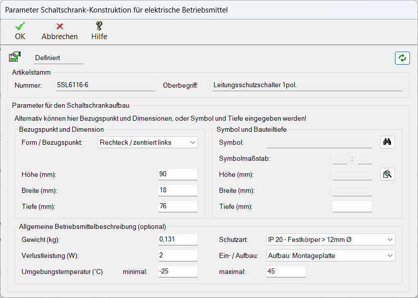
So there we have everything we need. Power dissipation, and minimum and maximum ambient temperatures—what more could you want?
Control Cabinet Parameters
The “Parameter – Control Cabinet Views” dialog box stores the following data: material, mass, width, height, and depth. This information is sufficient for the calculation.
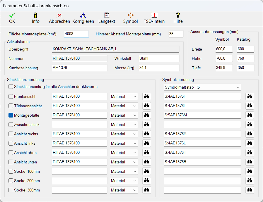
Select a Control Cabinet
When selecting a control cabinet, you can use the “Symbol via Catalog Tree” function and, if desired, display the long text as well. This text contains all the information you need to make the right selection.

Simultaneity factor
Next, we examined the simultaneity factor. This factor indicates the probability that all consumers in a system will, on average, be operating at full power at the same time. We found the following table on this topic.
Values for the assumed load
| Main circuits | Assumed load factor |
|---|---|
| 2 and 3 | 0.9 |
| 4 and 5 | 0.8 |
| 6 to 9 | 0.7 |
| 10 or more | 0.6 |
Heat Transfer Coefficients of Common Control Cabinet Walls
We looked into this as well and found the following figures:
| A | Painted sheet steel: U=5.5 W/(m²·K) | 05.50 | W/m²*K |
| B | Stainless steel sheet: U=4.5 W/(m²·K) | 04.50 | W/m²*K |
| C | Aluminum: U=12.0 W/(m²·K) | 12.00 | W/m²*K |
| D | Double-walled aluminum: U=4.5 W/(m²·K) | 04.50 | W/m²*K |
| E | Polyester: U=3.5 W/(m²·K) | 03.50 | W/m²*K |
| F | Stainless steel: U=3.7 W/(m²·K) | 03.70 | W/m²*K |
| A | K – Heat transfer coefficient for control cabinet | 05.50 | W/m²*K |
We’d also like to ask for your help with this. Anyone who can contribute is more than welcome.
Formulas for Calculating the Effective Surface Area of a Control Cabinet
We have researched the following formulas here:
| A | Single enclosure – freestanding on all sides | A (m²) = 1.8 × H × (B + H) + 1.4 × B × T |
| B | Single enclosure for wall mounting | A (m²) = 1.4 × B × (H + T) + 1.8 × T × H |
| C | Start or end housing – freestanding | A (m²) = 1.4 × T × (H + B) + 1.8 × B × H |
| D | Start or end housing for wall mounting | A (m²) = 1.4 × H × (B + T) + 1.4 × B × T |
| E | Center housing – freestanding | A (m²) = 1.8 × B × H + 1.4 × B × T + T × H |
| F | Center housing for wall mounting | A (m²) = 1.4 × B × (H + T) + T × H |
Sources:
Creating a Table
Based on the information gathered in the current state analysis, we developed a table.
Our goal is for all red fields to be filled in automatically based on the parameters stored in the master data, and for the green fields to be calculated automatically from those values.
For example, the “maximum temperature inside the control cabinet (Ti)” is determined by the equipment used with the lowest maximum ambient temperature.
We’ve currently focused on thermal calculations here. If any of you need to build control cabinets for Alaska, we’ll expand the formulas and develop a design tool for control cabinet climate control. If any of you need this—that is, if you also need to heat control cabinets—please let us know.
Your task is therefore limited to filling in the yellow fields.
Quality Assurance
We compared our calculations with the results from various tools, and the results were very promising. There were only very slight deviations of 0.5 °C.
What’s left to do?
Now we need to convert the table into Treesoft CAD dialogs and enter the corresponding formulas.
Create a Form Template
Last but not least, we’ll develop a form—similar to the templates for the bill of materials or terminal diagram—where we’d like to display the results. Please feel free to share your ideas and specific suggestions with us.
Closing Remarks
We have the best customers in the world—you—and we’re grateful for all your support.
Yours, Andreas
Project Manager: Paul Küstermann
Technical Director: Volker Kröll (who, by the way, is one of our customers)
Product Manager: Andreas Küstermann
Try Treesoft CAD
for free
Questions?
We're happy to help!
+49 2266 4763-800
sales@treesoft.de


