What's New – Treesoft CAD
Foreword
Treesoft CAD 7.1 includes many improvements, functional enhancements, and completely new features. In addition, the capabilities of the CAD core—which was newly developed for version 7.0—have been extensively utilized and further expanded.
General
New Drawing Header
Treesoft CAD 7.1 now supports all Unicode character sets. To this end, the data format of the drawing files has been expanded accordingly.
If you were to open a drawing file created with version 7.1 using an older version of Treesoft CAD, the program would inevitably crash. Knowing that we would certainly expand—and thus change—the data format after developing the new CAD core, we had already defined an identifier in version 6.4 that allows the program to recognize that the drawing file was created with a more recent version than the one currently in use. In this case, the following dialog box appears:
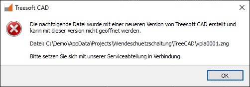
All older versions of Treesoft CAD do not recognize this identifier and therefore display the following message:

In both cases, automatically canceling the loading process prevents Treesoft CAD from crashing.
To be able to open a drawing file created with Treesoft CAD Version 7.1, you must therefore also install the 7.1 upgrade.
Conversion Moved to the Analysis Phase
In version 7.0, when a drawing file was opened, it was converted to the new data format. As a result, since version 7.0, drawings have been created with the highest possible precision (64-bit floating-point arithmetic). Since then, the Autoconnect feature has also worked with scaled and rotated symbols.
When saving, the drawings were converted back to the old data format because the analysis module did not yet support the new data format.
With the CAD 7.1 upgrade, drawings are saved in the new data format and with a new drawing header, as described above. The analysis tool now supports the new data format, at least in part, but not entirely. Where necessary, the analysis tool automatically converts the drawing into the required data format.
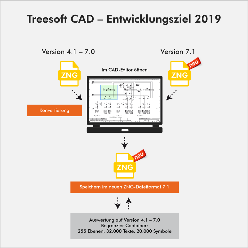

This means that conversions now only take place during evaluation and no longer every time a drawing file is opened or saved. In addition, this allows us to gradually transition the functions in the evaluation to the new data format, thereby progressively limiting the need for conversion. As always, of course, all of this happens completely unnoticed by you. Overall performance has improved significantly once again.
Set an icon on the catalog tree
By gradually transitioning from the Microsoft Foundation Classes (MFC) to the Qt application framework, we were able to significantly improve usability. One result of this is the new dockable windows in the [F2] Set Icon via Catalog Tree function.
The user interface is almost self-explanatory. The “Item,” “Graphic,” and “Name” buttons are no longer needed because the lists are now stacked on top of each other in different tabs. This gives you the option to detach the lists and drag them to a second screen. It is now also possible to display two lists side by side.
Place an icon over the library
Here, we’ve simply changed the command name from “Set Symbol” to “Set via Library.” Everything else, including the hotkey “S” and the F4 key, remains the same.
Dialog Text
With the Foreign Language Translation add-on module, Treesoft CAD now supports the use of all Unicode character sets, such as Cyrillic and Chinese characters.
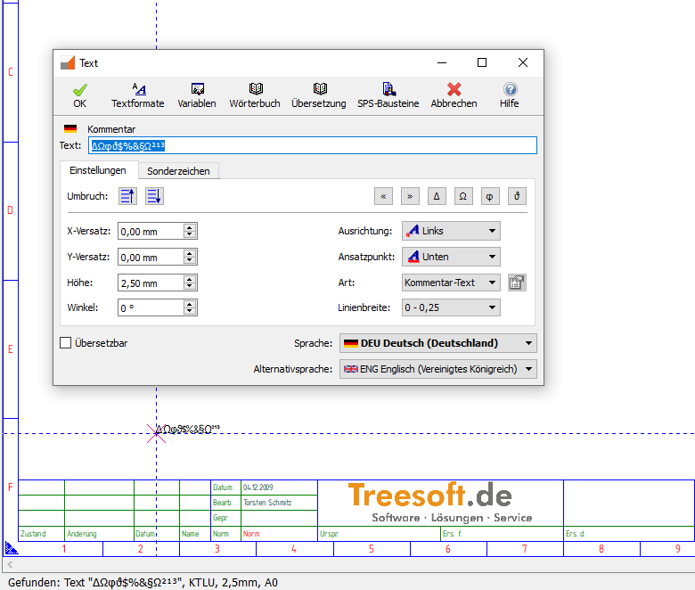
To allow you to edit these character sets in the text dialog as well, the dialog must also support Unicode. As part of this update, we have completely redesigned the dialog.

We have replaced the text blocks feature with the autocomplete feature. The autocomplete feature is more effective, and we are confident that you will enjoy using this convenient feature.
In the figure above, the drop-down list uses autocomplete to display all entries from the dictionary for the text’s native language that begin with the input “Sicherung.“
If the “Translatable” checkbox is selected, text can be displayed in the languages that have been configured.
Text display in the status bar, drawing, and dialog box
Text is now always displayed correctly in the status bar, on the screen, and in the text input dialog. Up to version 6.5, special characters were displayed correctly only on the artboard; starting with version 7.0, they are also displayed correctly in the status bar, and as of version 7.1, they are also displayed correctly in the Text dialog box, since it now supports Unicode.
The ISO 3098 character set is used
In the character set zeichen.set, the individual characters were created in the character set editor using lines, based on the standard typeface used at the time in accordance with DIN 16. When displayed on the screen, plotter, or printer, the text was rendered as lines. This allowed us, as early as 1986, to rotate text in degree increments, scale it up as desired, and output it with the desired line thickness. Furthermore, the output on a plotter or printer matched exactly what was displayed on the screen—in other words, WYSIWYG. At the time, this was a first on the market.
Using the `zeichen.set` during PDF export prevents you from searching for text, because the text is still rendered as lines during export. To prevent this, we’ve already added a feature in version 7.0 that allows you to output text using the ISO 3098 character set. Although we have scaled the ISO 3098 character set so that the output corresponds as closely as possible to the `zeichen.set`, unfortunately, 100% WYSIWYG functionality was lost.
In version 7.1, you can now also use the ISO 3098 character set to create drawings. The “zeichen.set” file is now largely obsolete and is included solely for compatibility reasons; the ISO 3098 character set is now always the default. This restores 100% WYSIWYG functionality.
Control Technology
Foreign Language Translation
The foreign language translation feature has been completely redesigned, and yes, you can now use Cyrillic and Chinese character sets as well.
To make this possible, the following functional enhancements were implemented:
The "Text" dialog box is now Unicode-compatible
The "Translate" dialog box is now Unicode-compatible
The "Dialog" "Dictionary" is now Unicode-compatible
Any Unicode-compatible TrueType and OpenType fonts can now be used in Treesoft CAD.
When you add a character set, it is automatically configured. This ensures that the proportions between the different character sets are consistent.
Each language must be assigned a corresponding character set. For example, in order to display text in Chinese, the language must, of course, be assigned a character set that includes all 60,000 Chinese characters.
Native language
Native language
For new projects, the first thing you do is assign a primary language—either German or English.
For existing projects, the prompt appears automatically when the first drawing file is opened.
Language and alternative language for output
Language and alternative language for output
The 7.1 upgrade has significantly improved translation performance. In Treesoft CAD 7.1, the source language and target languages are stored directly in the drawing file. This means there is now only one file containing all selected languages, rather than one drawing per language as in the previous version. Consequently, there is now only one file in which changes need to be maintained. The changes are then automatically applied to all selected output languages.
For on-screen display, printing, or PDF export, select an output language and an alternative language. You can select either one at any time.
For example, if you create a schematic in your native language (German) and want to output it in Chinese, but have only translated the items into English, then select Chinese as the language and English as the alternative language.
All texts for which a Chinese translation is available will be displayed accordingly. If no Chinese translation is available, the text will be displayed in English.
Auto-Complete Feature
Auto-Complete Feature
As you type, the text you enter is automatically completed. Treesoft CAD uses its built-in dictionary for this. This not only saves you a lot of typing, but also prevents incorrect translations caused by typos.
Plug-in Control Technology: A Cleaner Approach
Here, we have revised and improved the mapping of symbols and articles. This makes it easier for new users in particular to get up to speed.
Building Systems
Utility Line Installation
In particular, the installation of wiring across multiple floors and the calculation of cable lengths have been significantly improved.
Improvements to Connection Analysis
With the CAD 7.1 upgrade, you can now also scale the “Cable/Wire Connections” dialog box. This makes editing easier and more organized.
View and Delete a Line
View and Delete a Line
In addition, we have significantly improved the display and deletion of cable and line connections. When a line is now deleted via the Cable/Line Connections dialog box, the line segments that span multiple floors are also deleted.
Show Cable/Wire Connections
Show Cable/Wire Connections
Until now, clicking the “Show” button highlighted the currently selected connection in color on the building floor plan. All other connections were hidden.
Now click the “Display” button to switch to display mode. Here, too, the selected connection is highlighted in color (red). A new feature is that for cables that span multiple floors, the cable segments laid on the floor above or below are also displayed in green with a dashed line.
In addition, you can now move the selection cursor within the list to display the currently selected entry. This makes it easy to scroll through all entries and check the routing.
Improvements to Circuit Analysis
You can now also scale the Circuit List dialog. We’ve also significantly improved the ability to delete and view circuits.
Delete Circuit – Circuit List
When a circuit is deleted via the circuit list, all line segments—including those that span multiple floors—are now deleted.
Circuit Displays – Circuit List
Until now, clicking the “Show” button highlighted the currently selected circuit in color on the building floor plan. All other circuits were hidden.
Now click the “Display” button to switch to display mode. Here, too, the selected circuit is highlighted in color (red). A new feature is that for circuits that span multiple floors, the wire segments laid on the floor above or below are also displayed in color (green) and as dashed lines.
In addition, you can now move the selection cursor within the list to display the currently selected entry. This makes it easy to scroll through all entries and check the routing.
Info Function, Change Position Number
If you change the item number for a switch installed on the ground floor that is connected to a distribution panel in the basement, the updated item number will now also be displayed in the connection list and the circuit list. Up to Treesoft CAD version 7.0, this required deleting the line and rerouting it.
“Electrical” menu, “Delete Line” command
If you now delete a line using the Delete Line command in the Electrical menu, all line segments—including those that span multiple floors—will, of course, be deleted as well.
“Electrical” menu, “Delete Wiring Harness” command
If you now delete a wiring run using the Delete Wiring Run command in the Electrical menu, all segments of the wiring run—including those that span multiple floors—will, of course, be deleted as well.
Delete Floor Plan
We’ve improved the screen for deleting a floor plan. If you select a different floor plan from the “Select Floor Plan” list box, it will now be displayed immediately without any flickering. In the “Delete Floor Plan” dialog itself, traffic light colors—red for “unoccupied” and green for “occupied”—now indicate whether the corresponding level is occupied or not.
Copy Component
Previously, when copying, the rotation angle of the position number was not taken into account, and the position number was always placed with a rotation angle of 0 degrees after copying. We’ve improved this. Now, the position number is placed at its original rotation angle.
CAD Converter
The new PDF/DXF/DWG CAD converter was first released with Upgrade 6.4, Build 4 on June 15, 2015, and has been continuously improved ever since. We have continued to develop it in Upgrade 7.1 as well and have once again implemented some of the improvement requests you’ve shared with us. In particular, the enhancements to the bidirectional module significantly enhance building services engineering.
CAD Converters in General
Like Treesoft CAD, the CAD Converter now also operates on a project-by-project basis; that is, the CAD Converter now opens and saves files within the active project. If you open a PDF, DWG, or DXF file outside the active project using the “Open File” dialog, the original file is automatically copied to the active project when the ZNG file is exported. This improves usability and ensures that all files associated with the project are also saved within the project.
CAD Converter Bidirectional Module
You can now update a floor plan imported via the Bidirectional Module at any time.
The update is possible even if the scale and/or sheet format were previously changed in Treesoft CAD Building Services.
As part of the update, the export area can also be changed, and this is implemented correctly as well.
With this, we have implemented what is likely the most frequently requested feature from you all: a functional enhancement to the CAD converter.
The following video shows the possibilities this opens up for you.
Questions?
We’re happy to help!
+49 2266 4763-850 · support@treesoft.de


